Little Falls Tie Line Towers Historic American Engineering Record WA-82
This is a historic document which placed the Little Falls Tie Line in the Historic American Engineering Record WA-82. The format has been changed in two ways. First the two repositories, text and photographs, in the Library of Congress have been merged to give each other more context. Second, some liberty has been applied to the document to reorder the paper structure (especially continuation pages and some data field formatting). Footnotes have been converted to end notes. No data has been deleted and the originals are also accessible. Edit this document only to correct transcription and typographical errors.
The original document for the text form is here. The original document for the accompanying photographs is here.
HAER No. WA-82
Near Little Falls Dam on the Spokane River
Wellpinit Vicinity
Stevens County
Washington
PHOTOGRAPHS
WRITTEN HISTORICAL AND DESCRIPTIVE DATA
HISTORIC AMERICAN ENGINEERING RECORD
Little Falls Tie Line Towers HAER No. WA-82
| Location: | Beginning on the south bank of the Spokane River at Little Falls Dam, in the vicinity of Wellpinit, Lincoln County, Washington, heading ca. 24 miles in a southeasterly direction to the Spokane vicinity, Spokane County, Washington
U.S.G.S. 7.5 minute Little Falls, Long Lake, Four Mound Prairie, Deep Creek, and Airway Heights, Washington, quadrangles, Universal Transverse Mercator coordinates: 11.431300.5297700 and 11.461260.5276580 |
| Date of Construction: | 1910, crossarm alterations in 1911 |
| Manufacturer: | United States Wind Engine and Pump Company |
| Present Owner: | The Washington Water Power Company |
| Present Use: | Electrical transission, but slated for immediate design modification |
| Significance: | The Little Falls Tie Line Towers are significant as components of one of the trans-Mississippian West’s earliest steel tower transmission lines. This system distributed electrical power from
The Washington Water Power Company’s Little Falls Dam (a National Register of Historic Places property, 12/15/88) to the Spokane vicinity of eastern Washington, beginning in the early twentieth century. Its construction pioneered the use of steel towers for electrical transmission by utilizing modular units adapted from existing technologies of the U.S. windmill industry. In terms of engineering, the towers are unique as examples of the evolution in long distance transmission lines from wooden poles to metal structures, which facilitated regional hydroelectric development and resulted in wide-scale distribution of electrical power at affordable rates to urban Spokane and its outlying rural geographical region. |
| Report Prepared by: | Charles T. Luttrell Archaeologist Archaeological and Historical Services Eastern Washington University Cheney, Washington |
| Date: | February 1993 |
INTRODUCTION
The Washington Water Power Company’s (WWP) Little Falls Tie Line Towers are located between the company’s Little Falls Dam, near Spokane River Mile 30 in Lincoln County, and the vicinity of Spokane, Spokane County, Washington. The system of metal towers extends in a general southeast/northwest direction between these two end points through the two counties, in the northeastern portion of Washington State. As originally configured, the tower line stretched 28.14 miles with an average spacing of 650 ft between towers.[1] Between 1908 and 1910, WWP supervised the construction of the towers, which were the transmission component of the Little Falls Dam construction project. In the remaining 24-mile portion of the transmission line, 195 towers are presently extant. As observed in 1909:
When completed, the plant [Little Falls powerhouse] will develop 30,000 horsepower and will be hooked up with the company’s numerous plants in furnishing light and power to supply the Palouse country, the Big Bend, the Coeur d’Alene and the company’s other increasing demands for electrical light and power in Spokane and the Inland Empire.[2]
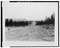
Preliminary design specifications for the transmission line were developed by the WWP in 1909, and by 10 August 1910, the majority of the line’s right-of-way clearing was complete (see photograph WA-82-9).[3] Tower design was predicated upon the need for economical field assembly of long-term low maintenance units of sufficient strength to support six transmission wires and two ground wires. Utilization of steel towers represents a departure from the period’s predominant use of wooden poles to facilitate electrical transmission. The United States Wind Engine and Pump Company of Batavia, Illinois, one of American industry’s premier windmill manufacturers, was awarded the contract for fabrication of tower parts. With the completion of the tower installation, initial service of the line began on 1 December 1910 with electrical
current delivered from Little Falls Dam to the 29th Avenue Substation in Spokane for local and regional distribution.[4]
As one of the Far West’s first steel tower electrical transmission lines, the Little Falls Tie Line Towers were to play an integral role in WWP’s hydroelectric power generation and integration of established electric companies located in the smaller towns surrounding Spokane into a single WWP-operated system. WWP policy at the time emphasized the acquirement of “light and power companies in the various towns served by the transmission lines of the Washington Water Power Company where they could be purchased on a fair valuation."[5] As reported by the WWP’s annual report of 1913 to its stockholders:
We believe that we can give better service and secure more satisfactory results, both to the customers and to the Company, by dealing directly with our consumers than under previous existing conditions and we expect also to increase the business in these districts.[6]
As a result of these policies, WWP consolidated ownership of numerous small utilities, increased its geographical service area, and lowered the per unit price of its electrical power. The Little Falls Tie Line Towers continued to distribute power generated at Little Falls Dam, as well as the additional load from the Long Lake hydroelectric facility after its completion in 1916. By exercising maximum control over generation and distribution of its hydroelectric power, as of 28 February 1914, WWP produced "hydraulic generated power at a lower cost than any other power company in the state.[7] WWP’s pioneering utilization of steel towers for the Little Falls Tie Line anticipated changes in electrical transmission technology which would come to dominate the use of transmission-related tower equipment to the present day. Although design modifications related to changing equipment needs of the system have occurred over the years, the remaining ca. 1910-era structures of the Little Falls Tie Line Towers retain excellent integrity and are representative of outstanding twentieth century industrial design.
STRUCTURE DESCRIPTION AND LAYOUT
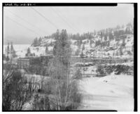
The Little Falls Tie Line Towers are considered as contributing elements of the Little Falls Dam’s historic transmission system.[8] As previously mentioned, this line extended from Little Falls Dam to the 29th Avenue Substation in Spokane, a distance of 28.14 miles. Each tower was assigned a numeric identification, beginning with tower No. 1 in closest proximity to Little Falls Dam (see photograph WA-82-1). It appears that the most easterly of the original steel towers of the Little Falls Tie Line was located 1.62 miles west of the substation (the remaining distance between the last metal tower and the substation was spanned by two wooden pole lines). At present, the line extends from the dam to a point on the north side of U.S. Route 2 (ca. three miles east of Airway Heights, Washington). The Little Falls Tie Line’s last steel tower is now located ca. 2.7 miles northwest of its historic point of termination. A total of between 200 and 400 individual towers were originally stipulated in the design specifications for the Little Falls Tie Line, although 225 towers were to compose the finished line.[9]
As noted by Boreson in 1992, "there are 196 towers in the remaining 24-mile portion of the original line," however, since that time tower No. 196 has been compromised, subsequent to a strength test referred to as a "pull test to destruction."[10] The test of tower No. 196 was performed to determine the structural viability of towers prior to installation of a new crossarm configuration. Although the tower was only expected to withstand a load of 10,000 lbs, tower collapse finally occurred under a force of 14,970 Ibs. At present, tower No. 195 is being utilized as an experimental tower to test various designs of crossarm configurations, but will, eventually, be dismantled and scrapped. WWP also plans to disassemble tower No. 194 and relocate it at its Jack Stewart Training Center for in-house training of present and future WWP linemen.
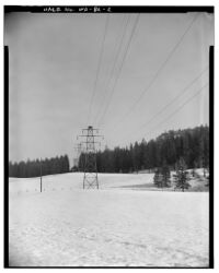
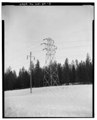
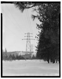
Of the remaining towers, only towers numbered 30-173 will be affected by the WWP’s planned modifications to the Little Falls Tie Line Towers. WWP’s proposed undertaking will adversely affect the integrity of the historic structures through construction of a new crossarm configuration. Towers numbered 4-29 and 174-193 will remain unaltered and retain their historic appearance (see photographs WA-82-2 and WA-82-3), with the exception that towers 174-193 will have their conductors and insulators removed. These towers have been “electrically dead" since 1990. As towers 194, 195, and 196 have been involved in modification evaluation, they will be removed during the current project undertaking.
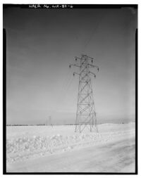
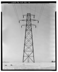
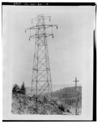
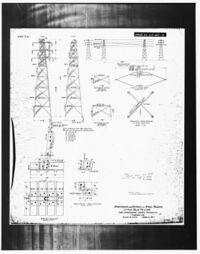
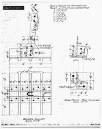
The towers of the Little Falls Tie Line are arranged as a series of four-legged pyramidal structures, fabricated from modular zinc-galvanized, "L"-shaped components (see photograph WA-82-6). Towers vary in height from forty to sixty feet tall, with fifty feet as the standard tower height. Individual tower height was dependent upon terrain and distance between towers, while crossarm configuration reflected each tower’s position along the line route. Anchorages for the towers are of two types: 1) for setting towers in soil or loose rock; and 2) for setting on top of solid rock. Both systems utilized variously shaped metal pieces to which each tower leg was bolted (see photographs WA-82-13 and WA-82-16).
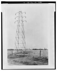
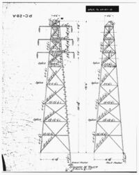
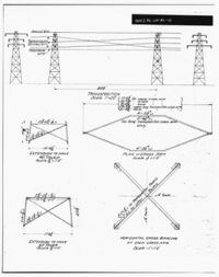
The body of each tower was field-erected by bolting differing lengths of leg sections together. Individual legs were then interconnected to each other by way of horizontal and diagonal cross bracing (see photographs WA-82-14 and WA-82-15). Series of bracing between each set of two legs extended from near the ground surface to the apex of each tower’s ridge-like top. Tower design was of two distinct types, standard towers and transposition towers. In the case of a standard tower, horizonal crossarms to carry the transmission wires were constructed as elongated hexagons with attachment points at the long ends of each crossarm for insulator hangers. Each standard tower, as originally designed, accommodated three crossarms of equal length, each vertically spaced seven feet apart and located in the upper third of each tower (see photograph WA-82-10).
A variation of the standard tower was historically referred to as a "peak" tower. Peak towers were located along the line at points of dramatic elevational change in the ground surface. As specified by the WWP:
A peak tower is determined as follows: - Add the difference in elevation between a given tower and the adjacent one on each side. When this sum is 40 feet or more the tower is taken as a peak tower.[11]
The Little Falls Tie Line contained thirty-eight peak towers. In terms of configuration, they differed from standard towers only by way of additional vertical and/or diagonal bracing to strengthen peak tower crossarms (see photographs WA-82-3 and WA-82-12). Towers in these positions were placed under increased physical load due to degree of elevational change. It appears that the slight structural changes which identified a peak tower as a distinct variation of the standard tower were adaptations which were made after 14 March 1912.[12]
The assembly of the transposition tower was similar to that of the standard tower, with the exception of the configuration of the three crossarms. Transposition towers were located at various points along the line in pairs, one tower configured with its bottom crossarm as the longest of its three arms and its tower mate having the top crossarm as the longest arm (see photographs WA-82-5 and WA-82-15). Eight pairs of transposition tower were distributed along the Little Falls Tie Line.[13] In terms of electrical engineering, transpositions were necessary, “to balance orientation of the three conductors [the 3 transmission wires on each side of the tower] relative to ground and each other, and [in an effort] to equalize the current in each of the conductors."[14] As specified by WWP, each tower assembly was to include:
...all necessary insulator hangers, ground wire clamps, bolts, nuts and washers, and shall be complete and ready to receive insulators and wires in the field. They shall be provided with metal steps to within eight feet of the ground line to permit linemen to ascend with safety to either circuit while the other circuit is alive.’[15]
Additionally, each tower was to be shipped from the manufacturer in a "knocked down" condition with:
...Similar members bound in bundles of approximately 100 pounds each, marked and labeled systematically for intelligent assembly. All small parts, such as bolts, nuts, washers, et cetera to be shipped in kegs or boxes packed individually for each tower. No bundle, keg or box shall contain parts of more than one tower.[16]
Installation of the transmission wires began upon completion of tower erection. Individual wires were connected to each tower’s six insulators by way of specialized cable clamps. It appears that WWP engineered several variations of clamp designs from wood and metal materials, and field tested these designs themselves.[17] With the initiation of electrical service in December of 1910, the Little Falls Tie Line was activated as a 60,000 V, double circuit line. As reported in the Spokesman-Review of 2 December 1910, "when the power was turned on yesterday morning the system was so complete no difficulty was experienced in transmitting the high voltage."[18] By 15 June 1911, specifications to increase the line’s load to 70,000 volts were being composed (a plan, it appears, that was never implemented), but using the existing electrical configuration:
Each pole [steel tower] shall be designed to support two (2) ground wires located at the top of the pole: six (6) transmission conductors located three (3) on each side of the pole; and two (2) telephone wires located below the transmission conductors, one (1) on each side of the pole... As further indicated on the above mentioned drawing No. 196-1A, the two (2) ground wires, which each steel tower will support, will be located at the top of the pole. . . . the six (6) transmission conductors, which each steel tower pole will support, will be located three (3) on each side of the pole. The three (3) transmission conductors on one side of the pole will form a single and electrically independent transmission circuit. Each transmission conductor will be nineteen (19) strand 270,000 c.m. Aluminum cable having an elastic limit of approximately three thousand (3000) pounds and an ultimate strength of approximately five thousand one hundred (5100) pounds.”[19]
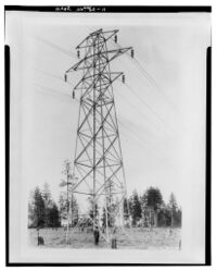
The 1910-completed structures were modified in 1911 after incidents of inclement weather during their first season of service revealed an unforeseen design flaw. Modifications to middle crossarms of standard towers were made by increased arm length to rectify the problem and the resultant change maintained a continuity of materials if not the original engineering design (see photographs WA-82-10 and WA-82-11). Periodic increases in the electrical generation capacity at Little Falls Dam resulted in increased utilization of the Little Falls Tie Line. Little Falls Dam’s original capacity was 15,000 kw, but due to a growing market demand, increased to 20,500 kw the following year.[20] Completion of Long Lake Dam in 1916 added an additional load source to the line from Little Falls Dam to Spokane. The Little Falls facility continued to evolve:
Other increases in output were made in 1924, 1930, and 1931. Generally this was accomplished by rewinding the generators and by the addition of a cooling system. Located four miles down-river from Long Lake and about thirty-five miles west of Spokane, the unit ties into the system a total operating capacity of 29,500 Kilowatts at the present time [ca. 1939].[21]
Electrical potential transmitted by the Little Falls Tie Line Towers is at present 115,000 V, almost double its original voltage. Modifications to accommodate the increased voltage were made in 1982. However, taken as whole, only minimum alterations, including the addition of insulation, have occurred to the line during its 82-year period of use.[22]
ALTERATIONS AND ADDITIONS
The winter of 1910-1911 served as the first operational trial of the new transmission line under cold weather conditions. Although precipitation was not excessive nor temperatures below average for this winter period, two rural inhabitants observed dramatic "flashing" along sections of the Little Falls Tie Line on 16 December 1910.[23] WWP investigations into the problem revealed that during an incident of air temperature warming, a large accumulation of ice dropped off one wire, thus allowing that wire to spring or rebound upward and in close enough proximity to the wire above it to start an arc. As a result of this unexpected situation, WWP subsequently began conducting "ice loading tests" to determine the effect of ice on the new Little Falls Tie Line. A 3 March 1911 report of testing results indicated that when the line’s bottom wire was severely loaded with weights between any two towers, sections of wire between the pair of towers on either side would indeed come into close proximity to the middle tie line wire.[24]
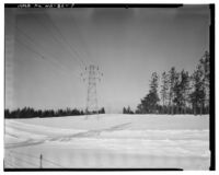
An additional set of tests was conducted by WWP at the 29th Avenue Substation on 13 July 1911. The object of these tests was to determine design changes which would alleviate the situation discovered the previous winter. In consequence, several arrangements of staggered crossarm lengths were installed and transmission lines weighted to simulate load stress. WWP concluded from these tests that the design utilized in the fourth test proved the most successful and easiest to install. This arrangement is visible on the Little Falls Tie Line Towers today, wherein a crossarm extension was added to the crossarm holding the middle transmission wire of standard towers (see photographs WA-82-7 and WA-82-10).”[25]
Heavy snows on 26 and 27 December 1911 occasioned investigations to determine the effectiveness of the new crossarm design under adverse weather conditions. The Little Falls Tie Line went "off line" on several occasions during this two-day period and crews were dispatched to knock snow off the lines.[26] In one instance, once the snow was removed from the middle wire, it rebounded above the top wire, but due to the new crossarm alignment there was no subsequent arcing between the two wires.
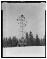
Review of Little Falls Tie Line historic photographs indicates that telephone lines were not attached to the towers as initially designed, but rather were strung on their own set of wooden poles which paralleled the length of the Little Falls line (see photograph WA-82-11). Additionally, some towers of the Little Falls Tie Line have become a favored location for osprey nesting. Osprey nests are located at the tower tops along several sections of the historic line (see photograph WA-82-4).”[27]
PRESENT CONDITION
The remaining Little Falls Tie Line Towers exhibit excellent integrity and continue to display an appearance relating to and defining their historic function. The design modification of added length to the middle crossarms of standard towers was necessitated by weather-inspired system failure during its first year of operation. These historic modifications are only one year younger than the towers themselves and reflect design "tinkering" of existing windmill technology to meet the specialized constraints of hydroelectric transmission. The need for a re-engineering of the Little Falls Tie Line Towers was revealed by field testing in severe weather conditions.
Because comparable materials and installation techniques were used in the 1911 modifications to the standard towers and the post-14 March 1912 alterations to peak towers, changes in tower design are not apparent to the casual observer (see photographs WA-82-10, WA-82-11, and WA- 82-12). The ease of modification, after testing of several options, would appear as one of the design strengths of modular unit-type construction which WWP appropriated for the Little Falls Tie Line Towers.
HISTORIC CONTEXT
Construction of the Little Falls Tie Line Towers by WWP accompanied completion of the Little Falls Dam facility, as the company pursued a policy to further develop the largely undeveloped hydroelectric potential of the Spokane River. While engineers in the first decade of the twentieth century promoted Washington State’s hydroelectric potential, historic observers had previously shared this understanding as well.[28] In the 1880s, for example, a U.S. Army officer observed:
The Spokane River, by its situation and characteristics, is bound to play an important part in the settlement and ultimate well-being of the whole country within a great distance of it. . . . The Spokane [River], in the upper part of its course, presents the estimable peculiarity - especially valuable in view of its use as a waterpower - of never freezing.[29]
At the time of Lieutenant Symons’ observations, James N. Glover and associates were operating a sawmill along the stretch of river at Spokan Falls, the 1881-incorporated town which was the historic forerunner to Spokane.[30] In 1873, Glover and company had purchased the mill site from the previous operators of a small crude mill, whose industrial endeavor dated from 1871 and marked the first important hydraulic development in the Spokane vicinity. Further utilization of the river’s waterpower continued with the development of additional mills and the first facilities for the production of hydroelectric power. In 1885, the Spokane Falls Electric- Light & Power Company built a small powerplant on the Spokane River’s north bank, a firm which was subsequently purchased by the Edison Electric Illuminating Company in 1888.[31] According to Hyslop, The Washington Water Power Company was organized in March of 1889 to build a generating plant along the Lower Falls locale in the heart of Spokane Falls and to acquire control of the Edison Electric Illuminating Company (by 1883, the growing community had experienced its first addition and name change by way of adding an “e," subsequently shortened to Spokane in 1891).[32] As of 1902:
Within the city limits of Spokane, and in close proximity to the manufacturing center, a series of falls are encountered by the Spokane river, aggregating a total of about 130 feet. The Washington Water Power Company owns and controls practically all of the available water power at that place, and furnishes power, either in the form of electrical energy, or by leasing a part of the water supply to parties wishing to use the same.[33]
The WWP continued its development of the Spokane River with an aggressive expansion policy which included construction of hydroelectric facilities outside of the city of Spokane. Constructed in 1906, the Post Falls plant, located on the Spokane River ca. 20 miles east of Spokane, was the first “out of town" development in the new construction program. The Little Falls Dam facility was completed next, in 1910. WWP had employed a work force of 264 men for dam construction, as well as "25 to 50 men" to improve the wagon road to the Little Falls Dam site during the 1909 construction period.[34] Located ca. 30 miles northwest of Spokane:
This plant [upon completion] contains four units, each consisting of 9000 h.p. I.P. Morris horizontal twin water wheel, direct connected to a 5500 k.v.a. 3- phase, 60 cycle, 4000 volt General Electric generator. The water wheels will develop a maximum of 11,250 h.p. each when operating under a 73 ft. head, running at 150 r.p.m. Each generator is guaranteed to operate continuously under 25 per cent overload.”[35]
The 15,000 kw produced by the Little Falls Dam facility increased WWP’s total system capacity by almost 50 percent.[36] Power generated at Little Falls was transmitted to Spokane via the Little Falls Tie Line, also completed in 1910. The WWP constructed the Post Street and 29th Avenue substations (both located in Spokane) in 1910-1911 to facilitate distribution of the increasingly available electricity. The 29th Avenue Substation, in particular, was significant in relation to the Little Falls Tie Line, as power delivered by the line was distributed from this high tension switching station to urban Spokane and outlying rural areas, the heart of a region often referred to as the Inland Empire. As defined by Fahey, the region is enclosed to the east and west by the Rockies and Cascade mountains, and bounded to the north and south by British Columbia and the Wallowa Mountains.[37]
Construction progress on the Little Falls project was reported in August of 1910:
The Little Falls plant is not as yet connected with the Spokane lines, the Spokane plant supplying sufficient power of the city traffic. The Little Falls plant is larger than the Spokane plant and, excepting while repairs or improvements or alterations are being made, the local plant will be used almost exclusively at first for the Inland Empire traffic outside of Spokane.[38]
The Little Falls Tie Line Towers of "bolted angle iron construction" were still unique in the WWP system as of 1915: “with the exception of this tower line, all high tension lines are of wooden pole construction."[39] Design distinction of the Little Falls Tie Line Towers was alternately addressed by a local newspaper in 1910 as "one of the first steel tower transmission lines for electricity in the northwest" and "the only steel tower transmission line in the west."[40] The Spokesman-Review further claimed: “this line . . . represents the latest practice in construction, heavy steel towers, similar to those used for windmills, being erected instead of the familiar wooden poles."[41] As the tower components were fabricated by the United States Wind Engine and Pump Company, the above comparison is not surprising.
Located in Batavia, Illinois, where "factories that line both banks of the [Fox] river manufacture windmills," United States Wind Engine and Pump Company had long maintained a position as major designers and manufacturers of windmills.[42] The company had its roots in the 1850s’ partnership between Daniel Halladay, an important nineteenth century American windmill designer, and John Burnham, an itinerant mechanic from New England. Originally known as the Halladay Windmill Company of South Coventry, Connecticut, Burnham soon moved a sales office to Chicago when he realized that the western United States would become the greatest market for windmills.[43] Burnham, along with Chicago entrepreneurs, organized the United States Wind Engine and Pump Company in 1857, with a determination to sell windmills produced in the Connecticut plant to the railroads for filling track-side water tanks.“[44] The Union Pacific was the first of the trans-Plains railroads to extensively use windmill technology for this purpose.[45]
The Halladay Windmill Company subsequently sold out to Burnham and associates in 1862, and the entire manufacturing business was moved to Batavia, a small town a few miles west of Chicago. The relocation allowed the company to take advantage of the industrial and transportation resources of the Chicago region, in an attempt to keep up with burgeoning national demand. The company was to open branch offices in Boston, Omaha, and Fort Worth, and "became the world’s leading manufacturer of windmills."[46] For a time, Batavia was known as America’s "windmill city," as five other windmill competitors also built factories here. The United States Wind Engine and Pump Company remained in business until 1951.
By 1903, American-made windmills were a significant export worldwide, with the exception of Europe. The industry had grown between 1879 and 1919 to employ 1932 employees, who produced $9,933,000 value of product in 1919, while during the same period, the number of windmill factories declined from 77 to 31.[47] In the view of Walter Prescott Webb, windmills were one of three important inventions that facilitated the rapid settlement of the Great Plains. The noted historian further contended that "the United States did for the windmill what it has done for the automobile," i.e., produced an affordable product available to the many.[48] As summarized by Webb:
The unique items of design (applying to towers also) that are the back of American windmill success are
1. Ability to be shipped knocked down and yet hastily erected with simple tools by ordinary mechanics.
2. Interchangeability of parts. 3. Durability.
4. Minimum amount of material used, keeping cost of material and transportation as well as erection down.
5. Simple lubrication.
6. Self-governing, both as to staying in the wind and as to maintaining a uniform speed regardless of velocity of wind.”[49]
There can be little doubt that WWP management also appreciated many of these design features, which in all probability influenced their choice of windmill technology for their Little Falls Tie Line Towers in the first place. By specifying zinc galvanizing for the towers’ steel parts, WWP, engineered low-cost maintenance for the towers over the life of their utilization. The pioneering use of what are essentially windmill towers for electrical transmission towers is ironic when one considers the evolution of the American windmill industry. By 1910, annual national use of windmills had yet to reach its 1919-1938 peak of 200,000 units of horsepower. For the same period, total horsepower produced by electric generating plants increased from 15,250,000 to 43,427,000 units.[50] Beginning in 1939, total horsepower generated by windmills would begin a steady decline to 1970 (when documentation ends) and reflected the growing utilization of electricity to fill the non-electric power niche once occupied by windmills. United States Wind Engine and Pump Company’s sale of towers to WWP no doubt added to total 1910 sales, but in effect, power industry use of their tower technology would increase the availability of hydroelectricity via long distance transmission to a growing market, at the windmill industry’s eventual expense.
With the initiation of the Long Lake hydroelectric facility construction in 1910, WWP continued to expand its electrical power generating capabilities. Located ca. 4.5 miles east of Little Falls, construction of the new development had commenced prior to completion of the Little Falls project. Power from the Long Lake plant eventually was connected to the Little Falls Tie Line for transmission to the 29th Avenue Substation, a major distribution station. By this time, WWP was actively engaged in developing a regional electrical system in eastern Washington, an expansion facilitated by consolidating smaller utilities, development of large-scale hydroelectric facilities, and construction of a distribution network of transmission lines.[51] The WWP’s expanding system was to result in the availability of low cost electricity to a large geographical service area which included Spokane, rural and small urban communities in eastern Washington, as well as communities and mining operations in northern Idaho.
As observed by Kensel, "by 1910 Spokane had literally become the hub of an empire with railroad lines, like the spokes, extending out from the city to the four points of the compass."[52] The regional economy was dominated by profits from agriculture, lumbering, and mining. However, availability of raw materials and exceptional rail access, combined with an abundance of hydroelectric generated power, were also establishing Spokane as the region’s industrial center. Distribution of WWP-controlled power imitated the pattern of the railroads, as transmission lines created a network connecting Spokane and the hinterlands of the Inland Empire.
While most WWP transmission lines were suspended from wood poles by ca. 1915, characteristics which they shared in common with the Little Falls Tie Line included crossing relatively short distances and low voltage. Although presently configured as a higher voltage line (115,000 V), the Little Falls Tie Line’s original 60 kV potential was considered average in 1924.[53] However, as foreseen at that time, "with the development of large blocks of power, higher transmission voltages will no doubt be used in the future."[54] The success of the Little Falls Tie Line Towers verified this prediction as steel tower construction became the power industry standard for the largest high voltage transmission lines.
SUMMARY
Construction of the Little Falls Tie Line Towers in 1910 represented the application of an advanced early twentieth century electrical transmission tower design. By adapting existing steel component windmill technology over the predominant practice of utilizing wooden poles, WWP produced a unique tower configuration. If not the first all-steel transmission line in the Far West, the tower design of the Little Falls Tie Line is certainly proto-typical of high voltage transmission towers prevalent later in this century. As part of WWP’s regional utility system, these structures contributed to the economic development of Spokane and outlying geographical areas of eastern Washington and northern Idaho through distribution of inexpensive hydroelectric power.
BIBLIOGRAPHY
Blewett, Steve. A History of the Washington Water Power Company: 1889-1989. Spokane: WWP, 1989.
Boreson, Keo. "Little Falls Tie Line." Determination of eligibility to the National Register of Historic Places, 1992. On file, Office of Archaeology and Historic Preservation, Olympia, Washington.
Bruce, Robin. "Long Lake Hydroelectric Plant." HAER No. WA-33, 1992. On file, Office of Archaeology and Historic Preservation, Olympia, Washington.
Fahey, John. The Inland Empire: Unfolding Years, 1879-1929. Seattle: University of Washington Press, 1986.
Federal Power Commission, “Reclassification of Electric Plant, Statements A to I, Inclusive," 1937. On file, Special Collections, Eastern Washington University Library, Cheney, Washington.
Federal Writers’ Project, Work Projects Administration. Illinois: A Descriptive and Historical Guide. Chicago: A.C. McClurg and Company, 1939.
Garfield, Leonard. Washington State Preservation Programs Coordinator. Correspondence to Robin Bruce of 15 January 1993. On file, Archaeological and Historical Services, Eastern Washington University, Cheney, Washington.
Hyslop, Robert B. Spokane’s Building Blocks. Spokane: Standard Blue Print Company, Inc., 1983.
Kensel, William Hudson. The Economic History of Spokane, Washington, 1861-1910. Ph.D. dissertation, Washington State University, Pullman. Ann Arbor: University Microfilms, 1972.
Lamar, R.W. WWP Employee. Correspondence to Mr. Wurtele of 17 January 1911. Engineering Department File No. 30-60-10-17.7. On file, WWP Transmission Department, Spokane, Washington.
Lamar, R.W. "Report of Snow Conditions on Little Falls Tie Lines: December 28, 1911." Engineering Department File No. 30-60-10-17.8. On file, WWP Transmission Department, Spokane, Washington.
Magnusson, Carl Edward. “Hydro-Electric Power in Washington." Part I, A Reconnaissance Survey. University of Washington Engineering Experiment Station Bulletin No, 26, 1924. Seattle: University of Washington. On file, Special Collections, Eastern Washington University Library, Cheney, Washington.
National Climatic Data Center. "Local Climatological Data: 1948 Annual Summary with Comparative Data, Spokane, Washington." 1948. On file, Anthropology/Geography Department, Eastern Washington University, Cheney, Washington.
Northwest Industrial Exposition. The City of Spokane Falls and its Tributary Resources. Buffalo: Matthews, Northrup & Company, Art-Printing Works, 1890. On file, Special Collections, Eastern Washington University Library, Cheney, Washington.
Shawen, Art. WWP Transmission Department Employee. Personal communication. 3 February 1993 and 24 February 1993.
Soderberg, Lisa. "Hydroelectric Power Plants in Washington State, 1890-1938." Multiple Property nomination to the National Register of Historic Places. 1988. On file, Office of Archaeology and Historic Preservation, Olympia, Washington.
Spokesman-Review, 2 April 1909:11; 29 May 1909:7; 4 August 1910:8; 10 August 1910:11; 2 December 1910:7; 14 December 1910:6; and 28 February 1914:7.
Symons, Thomas W. Report of An Examination of the Upper Columbia River and the Territory in Its Vicinity: In September and October, 1881, Executive Document 186, 47th Congress, Ist Session. Washington, D.C.: Government Printing Office, 1882.
Torrey, Volta. Wind-Catchers: American Windmills of Yesterday and Tomorrow. Brattleboro, Vermont: The Stephen Greene Press, 1977.
Uhden, C.F. System of Washington Water Power Company. San Francisco: Technical Publishing Company, 1915. On file, Washington State University Library, Pullman, Washington.
Webb, Walter Prescott. The Great Plains. Waltham, Massachusetts: Blaisdell Publishing Company, 1959.
Washington Geological Survey, Annual Report For 1901. Vol. 1. Olympia: State Printer, 1902.
WWP. "Preliminary Specifications for Steel Towers for Little Falls Tie Line of Washington Water Power Company." 12 July 1909. Engineering Department File No. 30-60-11-21.3. On file, WWP Transmission Department, Spokane, Washington.
WWP. "Report of Test on Wooden Cable Clamp To Be Used with Suspension Insulators." 17 June 1910. Engineering Department File No. 30-60-10-20. On file, WWP Transmission Department, Spokane, Washington.
WWP. “Report of Tests on Wooden Cable Clamp To Be Used with Suspension Insulators." 28 June 1910. On file, WWP Transmission Department, Spokane, Washington.
WWP. "Report of Tests on Wooden Cable Clamp To Be Used with Suspension Insulators." 1 July 1910. On file, WWP Transmission Department, Spokane, Washington.
WWP. "Tests to Determine Strength of Modified Little Falls Tie Line Steel Towers." Post-13 July 1911. Engineering Department File No. 30-60-11. On file, WWP Transmission Department, Spokane, Washington.
WWP. "Steel Pole Specifications." 1911. Engineering Department File No. 30-60-10-20.16. On file, WWP Transmission Department, Spokane, Washington.
WWP. "Ice Loading Tests on Little Falls Tie Line #1." 1911. Engineering Department File No. 30-60-13-21.3. On file, WWP Transmission Department, Spokane, Washington.
WWP. "Number of Peak Towers, Whose Cross Arms Are To Be Reinforced." 1912. Engineering Department File No. 30-60-10.11. On file, WWP Transmission Department, Spokane, Washington.
WWP. "Little Falls Tie Line Tower Locations." 1913. Engineering Department File No. 30- 60-10-21.3. On file, WWP Transmission Department, Spokane, Washington.
WWP. Commemorating A Half Century of Continuous Electric Service: 1889-1939. Post-1938. Spokane: WWP.
WWP. "Little Falls Tie Lines. No. 1 and No. 2." N.d. On file, WWP Transmission Department, Spokane, Washington.
United States Bureau of the Census. Historical Statistics of the United States, Colonial Times to 1970. Bicentennial Edition, Part 2. Washington, D.C.: U.S. Government Printing Office, 1975.
Route of The Washington Water Power Company Little Falls Tie Line Towers, February 1993. [[file:1993-loc-0006t-little-falls-power-lines-haer-wa-82-20.png
References
- ↑ 'The Washington Water Power Company (WWP), "Little Falls Tie Lines. No. 1 and No. 2," n.d.:1, WWP Transmission Department records, Spokane, Washington; C.F. Uhden, System of Washington Water Power Company, (San Francisco: Technical Publishing Company, 1915:10), Washington State University Library, Pullman, Washington.
- ↑ W.W.P. to Start Little Falls Dam," Spokesman-Review, 2 April 1909:11.
- ↑ WWP, "Preliminary Specifications for Steel Towers for Little Falls Tie Line of Washington Water Power Company," 1909, Engineering Department File No. 30-60-11-21.3, WWP Transmission Department records, Spokane; “Work is Rushing on Power Plant," Spokesman- Review, 10 August 1910:11.
- ↑ "New W.W.P. Power Line is Open," Spokesman-Review, 2 December 1910:7.
- ↑ Federal Power Commission, "The Washington Water Power Company: Reclassification of Electric Plant, Statements A to I, Inclusive," 1937:42, Special Collections, Eastern Washington University Library, Cheney, Washington.
- ↑ Ibid., p. 51.
- ↑ "Power Here Made the Cheapest," Spokesman-Review, 28 February 1914:7.
- ↑ Leonard Garfield, Washington State Preservation Programs Coordinator, correspondence to Robin Bruce, 15 January 1993, Archaeological and Historical Services project files, Eastern Washington University, Cheney, Washington.
- ↑ WWP, "Preliminary Specifications for Steel Towers for Little Falls Tie Line of Washington Water Power Company," 1909:2; WWP, "Little Falls Tie Line Tower Locations," 1913:5, Engineering Department File No. 30-60-10-21.3, WWP Transmission Department records, Spokane.
- ↑ Keo Boreson, "Little Falls Tie Line,” determination of eligibility to the National Register of Historic Places, 6 October 1992: Section 7:1, Office of Archaeology and Historic Preservation, Olympia, Washington, Art Shawen, WWP Transmission Department, personal communication with Robin Bruce concerning the Little Falls Tie Line Towers, 24 February 1993.
- ↑ "WWP, "Number of Peak Towers Whose Cross Arms Are To Be Reinforced," 1912:1, Engineering Department File No. 30-60-10.11, WWP Transmission Department records, Spokane.
- ↑ Ibid, p. 1.
- ↑ WWP, "Little Falls Tie Line Tower Locations," 1913:1-5.
- ↑ Art Shawen, WWP Transmission Department, personal communication with Charles T. Luttrell concerning transposition towers, 3 February 1993.
- ↑ WWP, "Preliminary Specifications for Steel Towers for Little Falls Tie Line of Washington Water Power Company," 1909:3.
- ↑ Ibid, p. 5.
- ↑ WWP, “Report of Test on Wooden Cable Clamp To Be Used with Suspension Insulators," 17 June 1910, Engineering Department File No. 30-60-10-20; "Report of Tests on Wooden Cable Clamp To Be Used with Suspension Insulators," 28 June 1910; "Report of Tests on Wooden Cable Clamp To Be Used with Suspension Insulators," 1 July 1910, WWP Transmission Department records, Spokane.
- ↑ "New W.W.P. Power Line is Open," Spokesman-Review, 2 December 1910:7.
- ↑ WWP, "Steel Pole Specifications," 1911:1, 2, Engineering Department File No. 30-60-10- 20.16, WWP Transmission Department records, Spokane.
- ↑ WWP, Commemorating A Half Century of Continuous Electric Service: 1889-1939 (Spokane: WWP, post-1938).
- ↑ Ibid, n.p.
- ↑ Boreson, "Little Falls Tie Line," 1992: Section 7:2.
- ↑ National Climatic Data Center, "Local Climatological Data: 1948 Annual Summary with Comparative Data, Spokane, Washington," 1948:12, Anthropology/Geography Department, Eastern Washington University, Cheney, Washington; R.W. Lamar, WWP employee, correspondence to Mr. Wurtele, 17 January 1911, Engineering Department File No. 30-60-10- 17.7, WWP Transmission Department records, Spokane.
- ↑ WWP, "Ice Loading Tests on Little Falls Tie Line #1," 1911:1, 2, Engineering Department File No. 30-60-13-21.3, WWP Transmission Department records, Spokane.
- ↑ WWP, "Tests to Determine Strength of Modified Little Falls Tie Line Steel Towers," post- 13 July 1911:1-6, Engineering Department File No. 30-60-11, WWP Transmission Department records, Spokane.
- ↑ R.W. Lamar, "Report of Snow Conditions on Little Falls Tie Lines: December 28, 1911," Engineering Department File No. 30-60-10-17.8, WWP Transmission Department records, Spokane.
- ↑ Rod Pharness, WWP Environmental Specialist, personal communication with Robin Bruce concerning osprey nesting, 9 February 1993.
- ↑ Robin Bruce, "Long Lake Hydroelectric Plant," HAER No. WA-33, 1992:10, Office of Archaeology and Historic Preservation, Olympia.
- ↑ Thomas W. Symons, Report of An Examination of the Upper Columbia River and the Territory in Its Vicinity: In September and October, 1881, Executive Document 186, 47th Congress, Ist Session. (Washington, D.C.: Government Printing Office, 1882:28, 29).
- ↑ William Hudson Kensel, The Economic History of Spokane, Washington, 1861-1910, Ph.D. dissertation, Washington State University, Pullman. (Ann Arbor: University Microfilms, 1972:171).
- ↑ Northwest Industrial Exposition, Spokane Falls, Washington, The City of Spokane Falls and its Tributary Resources (Buffalo: Matthews, Northrup & Company, Art-Printing Works, 1890:40).
- ↑ Robert B. Hyslop, Spokane’s Building Blocks (Spokane: Standard Blue Print Company, Inc., 1983:333).
- ↑ Washington Geological Survey, Annual Report For 1901, Vol.1, (Olympia: State Printer, 1902:311).
- ↑ "W.W.P. To Start Little Falls Dam," Spokesman-Review, 2 April 1909:11; "W.W.P. Widens Road," Spokesman-Review, 29 May 1909:7.
- ↑ Uhden, System of Washington Water Power Company, 1915:9.
- ↑ Steve Blewett, A History of the Washington Water Power Company: 1889-1989 (Spokane: WWP, 1989:22).
- ↑ John Fahey, The Inland Empire: Unfolding Years, 1879-1929 (Seattle: University of Washington Press, 1986:XI).
- ↑ "Turns on Power at Little Falls," Spokesman-Review, 4 August 1910:8.
- ↑ Uhden, System of Washington Water Power Company, 1915:10.
- ↑ "New W.W.P. Power Line Is Open," Spokesman-Review, 2 December 1910:7; "Support High Power Wires," Spokesman-Review, 14 December 1910:6.
- ↑ "Work Is Rushing on Power Plant," Spokesman-Review, 10 August 1910:11.
- ↑ Federal Writers’ Program, Work Projects Administration, Illinois: A Descriptive and Historical Guide (Chicago: A.C. McClurg and Company, 1939:536, 537).
- ↑ “Volta Torrey, Wind-Catchers: American Windmills of Yesterday and Tomorrow (Brattleboro, Vermont: The Stephen Greene Press, 1977:94). “Walter Prescott Webb, The Great Plains, (Waltham, Massachusetts: Blaisdell Publishing Company, 1959:338).
- ↑ Volta Torry, Wind-Catchers: American Windmills of Yesterday and Tomorrow",(Brattleboro, Vermont: The Stephen Greene Press, 1977:94).
- ↑ Webb, The Great Plains, 1959:348.
- ↑ Torrey, Wind-Catchers: American Windmills of Yesterday and Tomorrow, 1977:94.
- ↑ “Ibid, p. 88.
- ↑ Webb, The Great Plains, 1959:340.
- ↑ Ibid.
- ↑ United States Bureau of the Census, Historical Statistics of the United States, Colonial Times to 1970, Bicentennial Edition, Part 2 (Washington, D.C.: Government Printing Office, 1975:818).
- ↑ Lisa Soderberg, "Hydroelectric Power Plants in Washington State, 1890-1938," multiple property nomination to the National Register of Historic Places, July 1988: Section E:11, Office of Archaeology and Historic Preservation, Olympia, Washington.
- ↑ Kensel, The Economic History of Spokane, Washington, 1861-1910, 1972:88.
- ↑ Carl Edward Magnusson, “Hydro-Electric Power in Washington," Part I, A Reconnaissance Survey, University of Washington Engineering Experiment Station Bulletin No. 26 (Seattle: University of Washington, 1924:41, 42), Special Collections, Eastern Washington University Library, Cheney.
- ↑ Ibid, p. 43.
HISTORIC AMERICAN ENGINEERING RECORD
INDEX TO PHOTOGRAPHS
LITTLE FALLS TIE LINE TOWERS HAER NO. WA-82
Near Little Falls Dam on the Spokane River
Wellpinit Vicinity
Stevens County
Washington
| WA-82-1 | Contextual view of Little Falls dam, powerplant and northwest end of little falls tie line. Looking west. Harvey S. Rice, Photographer January 1993. | |
| WA-82-2 | View of west elevation of Little Falls tie line tower No. 23, osprey nest on tower top. Looking east. Harvey S. Rice, Photographer January 1993. | |
| WA-82-3 | View of northwest corner of Little Falls tie line tower
No. 23, standard peak tower. Looking southeast. Harvey S. Rice, Photographer January 1993. |
|
| WA-82-4 | View of southeast corner of Little Falls tie line tower No. 41, osprey nest on tower top. Looking northwest. Harvey S. Rice, Photographer January 1993. | |
| WA-82-5 | View of northwest elevations of Little Falls tie line towers No. 59 and No. 60, example of transposition towers. Looking southeast. Harvey S. Rice, Photographer January 1993. | |
| WA-82-6 | View of southeast elevation of Little Falls tie line tower No. 79. looking northwest. Harvey S. Rice, Photographer January 1993. | |
| WA-82-7 | View of southeast elevation of Little Falls tie line tower No. 130. looking northwest. Harvey S. Rice, Photographer January 1993. | |
| WA-82-8 | View of southeast elevation of Little Falls tie line tower No. 185. looking northwest. Harvey S. Rice, Photographer January 1993. | |
| WA-82-9 | Photocopy of 5 x 7 photograph enlarged from 4 x 5 negative (original print located in WWP
Building, Engineering Vault, Spokane, Washington). Photographer unknown, ca. Fall 1910. General view of Little Falls tie line right-of-way. Direction of view unknown. |
|
| WA-82-10 | Photocopy of 5 x 7 photograph enlarged from 4 x 5 negative (original print located in WWP
Building, Engineering Vault, Spokane, Washington). Photographer unknown, ca. Fall 1910. General view of Little Falls tie line standard tower (unmodified). Direction of view unknown. |
|
| WA-82-11 | Photocopy of 5 x 7 photograph enlarged from 4 x 5 negative (original print located in WWP Building, Engineering Vault, Spokane, Washington).
Photographer unknown, ca. May 7, 1913. General view of Little Falls tie line standard tower. Direction of view unknown. |
|
| WA-82-12 | Photocopy of 5 x 7 photograph enlarged from 4 x 5 negative (original print located in WWP Building, Engineering Vault, Spokane, Washington).
Photographer unknown, ca. May 7, 1913. General view of Little Falls tie line standard peak tower. Vicinity of Little Falls power plant in background. Direction of view unknown. |
|
| WA-82-13 | Photocopy of engineering drawing (original drawing
located in WWP Building, Transmission Department, Spokane, Washington). Dimensions and details of steel towers, Little Falls tie line. |
|
| WA-82-14 | Photocopy of engineering drawing (original drawing
located in WWP Building, Transmission Department, Spokane, Washington). Enlargement of standard 50' tower. |
|
| WA-82~15 | Photocopy of engineering drawing (original drawing
located in WWP Building, Transmission Department, Spokane, Washington). Enlargement of various tower details. |
|
| WA-82-16 | Photocopy of engineering drawing (original drawing
located in WWP Building, Transmission Department, Spokane, Washington). Enlargement of tower anchors. |

