Long Lake Dam Historic American Engineering Record WA-33-A
This is a historic document which placed Long Lake dam in the Historic American Engineering Record WA-33. The format has been changed in two ways. First the two repositories, text and photographs, in the Library of Congress have been merged to give each other more context. Second, some liberty has been applied to the document to reorder the paper structure (especially continuation pages and some data field formatting). Footnotes have been converted to end notes. No data has been deleted and the originals are also accessible. Edit this document only to correct transcription and typographical errors.
The original document for the text form is here. The original document for the accompanying photographs is here.
Long Lake Hydroelectric Plant
HAER No. WA-33-A
Spanning the Spokane River
Ford Vicinity
Lincoln and Stevens counties
Washington
PHOTOGRAPHS
"""WRITTEN HISTORICAL AND DESCRIPTIVE DATA
Historic American Engineering Record
Western Regional Office
National Park Service
U.S. Department of the Interior
San Francisco, California 94102
HISTORIC AMERICAN ENGINEERING RECORD
Long Lake Hydroelectric Plant
HAER No. WA-33-A
| Location: | Spanning Spokane River, .5 mile east of intersection with Washington State Route 231, ca. 5.0 miles south of Ford, Stevens and Lincoln counties, Washington |
| Date of Construction: | 1915 |
| Architect/Builder: | The Washington Water Power Company |
| Present Owner: | The Washington Water Power Company |
| Present Use: | Hydroelectric power generation and transmission |
| The Long Lake hydroelectric facility is significant as one of the earliest and, for many years, largest hydroelectric generating facilities in The Washington Water Power Company’s electrical power generating network. It is the largest hydroelectric facility on the Spokane River. Its construction played a vital role in facilitating the urban, industrial, and agricultural development of eastern Washington and northern Idaho. The Long Lake Dam possesses engineering significance as a reflection of advanced hydroelectric technology of the early twentieth century. It is architecturally important for the imposing Romanesque Revival style of its power house. The Long Lake Hydroelectric Plant and its setting have remained largely unaltered since original construction of the facility in 1915. The historic property was nominated to the National Register of Historic Places in 1988. Constituent elements include the spillway dam, control dam (intake), cut-off (arch dam), and the four brick operating houses situated on top of the spillway dam. | |
| Historian: | Robin Bruce Archaeological and Historical Services Eastern Washington University Cheney, Washington |
| Date: | May 1992 |
DESCRIPTION OF STRUCTURES
The Long Lake Hydroelectric Plant is a low-head gravity plant design with a dam that creates pondage at the point where the water is used. The dam creates a head of 170 feet, and impounds 4,573,800,000 cubic feet of water. The structure is built with the spillway section across the stream and the headgate section parallel to the river flow. The turbine-generator installed nameplate capacity rating is 70.000 kw. The brick power plant is constructed in the shape of a "T," with a concrete foundation and roof. Of Romanesque Revival styling, the power plant features arched fenestration set with large recessed arched panels.
The WWP’s proposed undertaking will alter character defining features of the spillway dam, including the control gates, operating houses, and operating mechanisms for the gates. These structures are described below:
The Spillway Dam The gravity spillway dam is 250 feet high from foundation to crest, 250 feet thick at its base and measures ca. 350 feet in length, and features cyclopean masonry construction in which ca. 25 percent of the dam is large rock. The spillway dam rests on a solid rock foundation.[1]
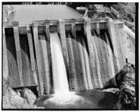
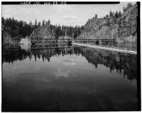
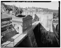
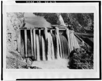
Massive curved concrete piers separate the paired control gates, with the two piers in the central portion of the spillway rising to observation parapets enclosed by protective chain link fencing (see HAER Photographs WA-33-A-1, WA-33-A-2, and WA-33-A-3). Four small brick operating houses shelter operating mechanisms and operator control panels for the eight spillway gates.
The WWP’s proposed project will create new visual effects to the spillway dam as a result of removal of the four existing brick operating houses and construction of the proposed 35 foot high cable hoist lifting mechanism. The concrete parapets above the spillway piers will be modified by the partial removal of concrete, beginning with the parapets’ arched access passages to the upriver crest of the spillway dam. The appearance of the parapets from the primary facade (spillway) will remain essentially unaltered.
Control Gates
Original design of the spillway control gates called for two fixed-wheel, vertical-lift “waste gates" (gates 1 and 2 are located on the east end of the spillway), which were installed before completion of the spillway dam in 1915.[2] In addition, the spillway was designed for four 65 foot openings that were originally designed for installation of drum gates of German design. However, because of events leading up to World War I (1917- 1919), the German gates could not be obtained.[3] The project, therefore, operated without the gates until 1919, at which time intermediate concrete piers were constructed in two of the rolling gate bays. Vertical lift gates 3 through 6, each measuring ca. 25 x 19 feet, were subsequently installed in the four bays (central portion of the spillway), A timber bulkhead occupied the west rolling gate bay until 1930 when the bulkhead was replaced with two vertical lift gates and intermediate concrete pier (see Alterations and Additions section of the report).
Gates 1 and 2 vary significantly in their configuration from gates 3 through 8. Gates 1 and 2 operate by a wheel retraction device, which allows the gates to move downstream onto their seals. The system has never proven satisfactory, however, with the result that control gates 1 and 2 have reportedly not been opened since 1948, and are currently operable only with supplemental hoisting assistance.[4]
Installed in 1919, Gates 3 through 6 are normally operated during excessive water flows. These gates do not feature a wheel retraction mechanism. The wheels are fixed and non-adjustable. The side seals are flexible and slide along the sealing surface when the gate is moved.[5]
Gates 1 through 6 are structurally similar:
The gates are of an unusual design wherein the upstream skin plates are not flat, but are warped between supports. This permits the skin to be loaded in tension along and to carry no bending moment. Gates 1 through 6 have skin plates which are warped both horizontally and vertically to form approximately spherically shaped bulges between supports [buckle plates]. The arrangement made possible thin skin plates (3/8 and 1/4 in. throughout) and corresponding very lightweight gates [ca. 50,000 pounds each].[6]
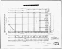
Gates 7 and 8 differ structurally from the other six gates, in that the buckle plate skin is warped in a vertical direction only (see HAER Photograph WA-33-A-13). This design resulted in slightly heavier gates (ca. 52,000 pounds each).[7]
Because of raised pool levels (see Alterations and Additions section of this report), age, and reliability, WWP. plans to replace all eight control gates with new steel roller gates beginning in June of 1992.
Operating Houses
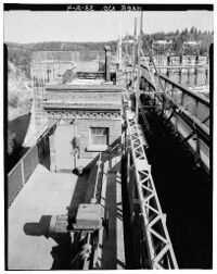
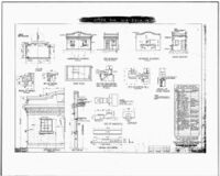
Four brick operating houses shelter gate operation mechanisms and operator control apparatus for the eight control gates. Each of the four structures is situated above the center piers of every pair of gate openings (see HAER Photograph No. WA-33-A-2). The operating houses were constructed following completion of the dam. Erected between 1915-1918, operating house 1 is the oldest of the four structures. Operating houses 2 and 3 were constructed in 1918 (see HAER Photograph No. WA-33-A-15 for plans of those structures), and operating house 4 was completed in 1930.[8] The operating houses measure ca. 17 feet x 10 feet, with the buildings’ facades facing the spillway. The operating houses are accessed from wooden side entry doors. Of eclectic styling, the flat-roofed structures feature metal-framed, multi-pane windows with concrete aprons. The curved, shaped crest of each of the four operating houses contrasts pleasingly with the linear honeycomb brickwork of the cornices. The four operating houses and the gate operating mechanisms that they shelter will be removed in order to accommodate the new cable hoist gate lifting tower.
Operating Mechanisms
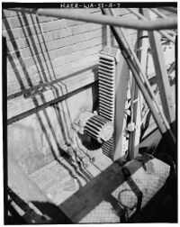
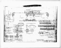
The control gate mechanisms consist of an array of shafts, gears, and motors (see HAER Photograph No. WA-33-A-16) which seat and unseat the spillway dam control gates:
Seating and unseating of the gate is brought about by simultaneous rotation of all the eccentric axles, which is accomplished by connecting all the axles through levers to a common bar, this bar being raised or lowered to cause rotation of ales. Motion is imparted to the common bars by connecting them to screws, one on each side of gate, the screws being raised or lowered by a bronze nut fixed in a bevel gear. This bevel gear is actuated through suitable gearing by a motor mounted on top of [the] gate for the purpose.[9]
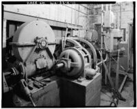
Hoist motors are General Electric three-phase, 60 cycles, 220 V., rated at 20 HP, 900 RPM, with a synchronous speed of 760 RPM. A limit switch is mechanically linked to the worm wheel shaft and connected electrically into the operating oil circuit of the hoist motor. This mechanism controls the vertical travel of the gate by opening the motor circuit at each limit (ca. 25 feet) of gate travel.[10] Each operating house originally consisted of an east and west motor and gear assembly connected by a drive shaft to a similar gear assembly located outside the operating house. The paired motor-gear assemblies were configured to simultaneously lift each respective gate to the gated pair. In 1989, the original motors for gates 3 through 6 were abandoned in place (see HAER Photograph No. WA-33-A-11), and replaced with new drive motors at the center of the gates (see HAER Photographs No. WA-33-A-4).[11]
The original specifications for the waste gate operating mechanisms indicate the type of fabrications used in the manufacture of those components and their production standards:
Main pinion shafts and intermediate shafts shall be of Open Hearth Steel, heat treated and shall conform in particular to the Specifications of the American Society for Testing Materials as adopted August 21st, 1911. All other shafting shall be of cold rolled steel. The worm gearing shall be enclosed in cast iron oil tight housings equipped with ball and roller thrust bearings on worm haft and bronze thrust washers on worm wheel shafts. Worms shall be of the "Hindly" type, carbon steel, case hardened, or tempered. Worm wheel rims shall be of Cramp’s Gear Metal No. 2 securely attached to wheel web... . All spur gears with the exception of gate pinions, shall have cut teeth. All bearings shall be babbited and provided with suitable oil grooves and oil chambers or compression grease cups.[12]
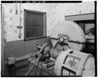
Most of the operator electrical control panels and manual control apparatus are located inside the operating houses. These mechanisms include control gate motor selector switches, lower magnetic contactors, raising magnetic contactors, hand brakes, motor clutches, gate limit transfer switches, and oil circuit breakers to gate motors (see HAER Photographs WA-33-A-10 and WA-33-A-11).[13]
BIBLIOGRAPHY
Bechtel Corporation. Report prepared for The Washington Water Power Company (WWP). "Long Lake Renovation Study--Spillway Gate Report," 1990.
Schlect, Ed. Project Engineer, Washington Water Power Company (WWP. Personal communication April 9 and May 8, 1992.
Soderberg, Lisa. “Long Lake Hydroelectric Power Plant," nomination to the National Register of Historic Places, October 12, 1988. On file in the Washington State Office of Archaeology and Historic Preservation, Olympia, Washington.
Uhden, C. F. "System of the Washington Water Power Company." Journal of Electricity, Vol. 33, No. 10, September 5, 1914.
Washington Water Power Company (WWP). “Historical Cost for Long Lake Spillgates and Control Houses." Accounting Department, WWP, Spokane, Washington.
WWP. "Notes on the Design of Waste Gates--Long Lake," n.a., January 3, 1916. WWP archives, Spokane, Washington.
WWP. "Operating Mechanism for Waste Gate," n.a., January 18, 1916. WWP archives, Spokane, Washington.
WWP. "Specifications for Waste Gate Hoist Mechanism at Long Lake Station," December 20, 1917. WWP archives, Spokane, Washington.
WWP. R. T. Tiffany, Washington State Supervisor of Hydraulics. Correspondence to the WWP of August 15, 1928, WWP archives, Spokane, Washington
WWP. “Operating Instructions July 30, 1957, for Long Lake Power Plant." WWP archives, Spokane, Washington
References
- ↑ C. F. Uhden, "System of the Washington Water Power Company," Journal of Electricity, Vol. 33, No. 10, September 5, 1914:4.
- ↑ "Long Lake Renovation Study--Spillway Gate Report," Bechtel Corporation for the WWP, 1990:2-1. Long Lake Hydroelectric Plant, Spillway Dam
- ↑ R. T. Tiffany, Washington State Supervisor of Hydraulics, correspondence to the WWP of August 155, 1928, WWP archives, Spokane, Washington
- ↑ "Long Lake Renovation Study," 1990:2-1, 3-1
- ↑ "Long Lake Renovation Study," 1990:3-1
- ↑ “Long Lake Renovation Study," 1990:3-2
- ↑ "Long Lake Renovation Study," 1990:3-1, 3-2
- ↑ "Historical Cost for Long Lake Spillgates and Control Houses," Accounting Department, WWP, Spokane, Washington, 1992:n.p.
- ↑ “Notes on the Design of Waste Gates~Long Lake," n.a., January 3, 1916:9. WWP archives, Spokane, Washington
- ↑ "Operating Mechanism for Waste Gate," n.a., January 18, 1916:n.p. WWP archives, Spokane, Washington
- ↑ Ed Schlect, Project Engineer, WWP. Personal communication May 8, 1992.
- ↑ "Specifications for waste Gate Hoist Mechanism at Long Lake Station," December 10, 1917:n.p., WWP archives, Spokane, Washington.
- ↑ "Operating Instructions July 30, 1957 for Long Lake Power Plant." WWP archives, Spokane, Washington.
HISTORIC AMERICAN ENGINEERING RECORD
Index to Photographs
Long Lake Hydroelectric Plant, Spillway Dam
HAER No. WA-33-A
Spanning the Spokane River
Ford Vicinity
Stevens and Lincoln counties Washington
NOTE: Photographs were taken by Harvey S. Rice, photographer, April 1992
| WA-33-A-1 | Contextual view of the spillway dam, control gates, and Long Lake reservoir, looking southwest. Photograph taken by Harvey S. Rice, photographer, April 1992. | |
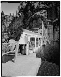
| WA-33-A-2 | Contextual view of the Long Lake reservoir, steel truss walkway bridge, and spillway dam, looking north. Photograph taken by Harvey S. Rice, photographer, April 1992. | |
| WA-33-A-3 | Detail view of operating house no. 3 for spillway gates 5 and 6, with control gates in background, looking southwest. Photograph taken by Harvey S. Rice, photographer, April 1992. | |
| WA-33-A-4 | Detail view of operating house no. 3 for control gates 5 and . Photograph taken by Harvey S. Rice, photographer, April 1992. | |
| WA-33-A-5 | Exterior view of the rack and pinion hoisting mechanism for no. 2 control gate, in foreground, with coping and cornice of operating house no. 1 visible in background, looking east. Photograph taken by Harvey S. Rice, photographer, April 1992. | |
| WA-33-A-6 | View of drift shaft, hoist motor, worm wheel gear assembly, cross shaft, and intermediate gear hoist assembly for control gate no. 6, looking west. Photograph taken by Harvey S. Rice, photographer, April 1992. | |
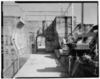
| WA-33-A-7 | Detail view of rack section and drive pinion hoisting assembly extending through the west wall of operating house no. 2 for control gate no. 4, looking east. Photograph taken by Harvey S. Rice, photographer, April 1992. | |
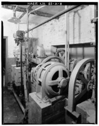
| WA-33-A-8 | Interior view of operating house no. !, showing original 20 hp west hoist motor, no. 2 control gate hand brake in foreground, bank of electrical control panels, and worm wheel gear assembly (right foreground), looking east. Photograph taken by Harvey S. Rice, photographer, April 1992. | |
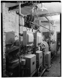
| WA-33-A-9 | Interior view of operating house no. i, showing detail of electrical control panels, worm wheel gear assembly, and no. 1 control gate hand brake, looking west. Photograph taken by Harvey S. Rice, photographer, April 1992. | |
| WA-33-A-10 | Interior view of operating house no. 4, showing original 20 hp west hoist motor (right foreground), worm wheel gear assembly, and motor gear, looking east. Photograph taken by Harvey S. Rice, photographer, April 1992. | |
| WA-33-A-11 | Interior view of operating house no. 4, showing worm wheel gear assembly, original 20 hp east hoist motor, and control gates 7 and 8 hand brakes, with motor selector switch, motor starting switch, and oil circuit breaker in background. Photograph taken by Harvey S. Rice, photographer, April 1992. | |
| WA-33-A-12 | Spillway dam and operating houses in 1923. Photographer is unknown. | |
| WA-33-A-13 | 1930 Gate installation details of control gates 7 and 8. This is a photocopies of drawings, courtesy of the Washington Water Power Company, Spokane, Washington. | |
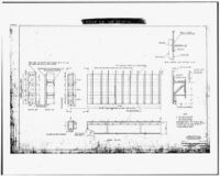
| WA-33-A-14 | 1949 Drawing of control gates 3, 4, 5, and 6, showing gate extension details. This is a photocopies of drawings, courtesy of the Washington Water Power Company, Spokane, Washington. | |
| WA-33-A-15 | Plans of the 1918 installation of operating houses 2 and 3 for control gates 3, 4, 5, and 6. This is a photocopies of drawings, courtesy of the Washington Water Power Company, Spokane, Washington. | |
| WA-33-A-16 | Plans showing the general arrangement of gate operating mechanisms. This is a photocopies of drawings, courtesy of the Washington Water Power Company, Spokane, Washington. |
