Long Lake Dam National Registry of Historic Places
This is basically a historic document concerning the registration of Long Lake dam as a National Registered Historic Place. The format has been changed in two ways. First the two repositories in the Library of Congress have been merged to give each other more context. Second, some liberty has been applied to the document to remove the paper structure (especially continuation pages and some data field formatting). Footnotes have been converted to end notes. No data has been deleted and the originals are also accessible. Edit this document only to correct transcription and typographical errors.
The original document for the text form only is here.
NPS Form 10-900 (Rev. 6-86)
OMB No. 1024-0018
United States Department of the Interior
National Park Service
National Register of Historic Places
Registration Form
This form is for use in nominating or requesting determinations of eligibility for individual properties or districts. See instructions in Guidelines for Completing National Register Forms (National Register Bulletin 16). Complete each item by marking "x" in the appropriate box or by entering the requested information. If an item does not apply to the property being documented, enter ‘N/A’ for ‘‘not applicable.” For functions, styles, materials, and areas of significance, enter only the categories and subcategories listed in the instructions. For additional space use continuation sheets (Form 10-900a). Type all entries.
1. Name of Property
historic name Long Lake Hydroelectric Power Plant
other names/site number N/A
2. Location
street & number Spokane River [_]not for publication
city, town Ford [x] vicinity
state_ Washington code WA county Stevens/Lincoln code 065/043 zip code 99013
3._Classification
Ownership of Property
[x] private
[_] public-local
[_] public-state
[_] public-Federal
Category of Property
[_] building(s)
[x] district
[_] site
[_] structure
[_] objects
Number of Resources within Property
| Contributing | Noncontributing | |
|---|---|---|
| 1 | buildings | |
| sites | ||
| 5 | structures | |
| objects | ||
| 6 | 0 | Total |
Name of related multiple property listing: Hydroelectric Power Plants in Washington State
Number of contributing resources previously listed in the National Register: 0
4. State/Federal Agency Certification
As the designated authority under the National Historic Preservation Act of 1966, as amended, I hereby certify that this [x] nomination [_] request for determination of eligibility meets the documentation standards for registering properties in the National Register of Historic Places and meets the procedural and professional requirements set forth in 36 CFR Part 60. In my opinion, the property [x] does [_] does not meet the National Register criteria. [_] see continuation sheet.
Signature of certifying official: Jacob E. Thom
Date: October 12, 1988
State or federal agency and bureau: Washington State Office of Archaeology & ]Historic Preservation
In my opinion, the property [_] meets [_] does not meet the National Register criteria. [_]see continuation sheet.
Signature of commenting or other official:
Date:
State or Federal agency and bureau:
5. National Park Service Certification I, hereby; certify that this property is: [x] entered in the National Register. [_] see continuation sheet.
[_] determined eligible for the National Register. [_] see continuation sheet.
[_] determined not eligible for the National Register.
[_] removed from the National Register.
Signature of the keeper: Delores Byen
Date of Action: 12/15/1988
6. Function or Use
Historic Functions (enter categories. from instructions)
INDUSTRY/energy facility
Current Functions (enter categories from instructions)
INDUSTRY/energy facility
7. Description Architectural Classification (enter categories from instructions)
Romanesque Revival
Other/industrial
Materials (enter categories from instructions)
foundation concrete
walls concrete, brick
roof concrete
other
Describe present and historic physical appearance.
The Long Lake Hydroelectric Power Plant is located on the Spokane River, four and one-half miles upstream from the Little Falls plant at a point where vertical rock walls rise 400 feet above the river. The dam creates a head of 170 feet, and impounds 2,695,000,000 cubic feet of water. That immense storage reservoir provides an endless source of water for power generation to both the Little Falls and Long Lake plants.
The layout of the Long Lake plant conforms to typical low-head plant design with a dam that creates pondage at the point where the water is used. In this design, a large volume of water passes through a short conveyance system to the turbines. The dam consists of a spillway and a headgate section. It is a gravity dam which sustains the water load entirely by the weight of the masonry. The dam features cyclopean masonry embedded in concrete mortar. To insure a watertight structure, and to relieve any upward pressure on the dam, an elaborate drainage system was constructed throughout the foundation.
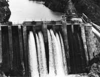
The spillway is 400 feet long, and crosses the entire breadth of the river. The structure, which measures 208 feet high, was the tallest spillway in existence when it was built. During flood periods it carries about 19 feet of water over its crest.
Flood waters are discharged and the water level in the lake is regulated by means of three rolling gates. The mechanical principle underlying the operation of the gates is suggested by the name. The weir body is opened or closed by rolling on an inclined track. Each roller consists of a steel cylinder that is 72 feet long and 11 feet 6 inches in diameter. A gear at each end of the cylinder engages a rack laid in an inclined recess in a concrete pier below the cylinder. The dam is rolled up or down by means of a sprocket chain which wraps around the cylinder and the operating mechanism. This type of gate had been used extensively throughout Europe but when installed at Long Lake it was considered the first application of the technology in the United States.
A 240 foot long headgate dam is perpendicular to the spillway section. As is typical of low-head installations, the intake forms part of the dam. The 21 by 19 foot headgates, constructed of I-beams and plates, regulate the flow of water into the penstocks. The 236 foot long penstocks convey the water a short distance to the turbine casing under a head of 170 feet. Their 16 foot diameter permits the flow of the large volume of water necessary to operate the turbines.
The turbines are direct connected to 13,900 KVA General Electric generators. Originally, each generator was supplied with a bank of three single-phase, 6,500 KVA water-cooled transformers which raised the voltage from 4,000 to a voltage of 63,600.
[x]see continuation sheet
NPS Form 10-6008 (OMB Approval Mo, 1024-0018
United States Department of the Interior
National Park Service
National Register of Historic Places
Continuation Sheet
Section number __7 _ Page __2__
The following inventory describes the constituent elements of the plant:
Dam (1915): consists of a spillway, headgate, and a cutoff or arch dam. The dam is constructed of cyclopean masonry founded on solid rock. The spillway dam measures 208 feet high from foundation to crest, 250 feet thick at the base, and 400 feet long. The headgate dam is 100 feet high, 100 feet thick at the base, 18 feet thick at the top, and 240 feet long. The arch or cutoff dam crosses a gulch about 900 feet above the spillway section, and measures 100 feet high, 50 feet thick at the base, 5 feet thick at the top, 540 feet long, and the radius of the upstream face is 170 feet.
Headgates (1915): twenty-one by 19 feet, constructed of I-beams and plates, and operated on wheels which travel on a vertical 60 pound rail concreted into the face of the dam. The main gate mechanism is driven by a 25 hp series motor.
Control Gates (1915): consists of three rolling gates and two gates, 25 feet long by 19 feet high, that are similar to the head gates in design. The rolling gates provide an opening 65 feet in length and 19 feet in height, and are separated by concrete piers 15 feet wide.
Operating Houses (1915): three brick and concrete structures above the control gates which house the operating mechanism for the control gates.
Penstocks (1915): steel, riveted; measures 236 feet long, 16 feet in diameter at the upper end and tapering to 14 feet 10 inches at the lower end. Plates vary in thickness from 15/16 inches at the lower end to 1/2 inches at the upper end, with 6 by 8 3/4 inch stiffener angles space five feet apart. No relief valve or surge tanks are used.
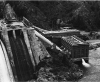
Powerhouse (1915): the powerhouse structure is a T-shaped, Romanesque Revival style structure with a concrete foundation, steel frame, brick exterior, and concrete roof. The building features round arched fenestration, with steel sash windows, set within large recessed round arched panels. The round arches are echoed in the arcaded corbel table. The building also features a flat roof with a parapet and a facade flanked by towers. The interior is characterized by plaster walls with tile wainscoting and flooring.
The generator and wheel room is located in the single story wing, measuring 75 feet by 160 feet and 65 feet high. The transformer switchboard and the high tension rooms are in a three story section of the building (the top of the "I") which measures 86 feet by 207 feet and 87 feet high. Originally transformers were located in brick compartments one floor above the main floor level, with openings toward the generator room. Behind the transformers are the machine shop and storage rooms. The switchboard gallery is located directly above the transformer compartments. Originally, the low tension bus structure was located adjacent to the switchboard gallery.
The high tension oil switches, disconnecting switches, and the high tension buses were located on the second floor above the machine shop. The lightening arrestors were located on the third floor. The storage battery was placed on the mezzanine floor of the machine shop. The generator and wheel room are served by a 90 ton Cleveland Crane with a three phase motor, and the high tension rooms are served by a 6,000 pound capacity elevator.
NPS Form 10-6008 (OMB Approval Mo, 1024-0018
United States Department of the Interior
National Park Service
National Register of Historic Places
Continuation Sheet
Section number__7____ Page __ 3
The transportation of the equipment was facilitated by a railroad track in the generator room directly under the crane.
Turbines (1913, 1915, 1917, 1924): the four 22,500 hp 200 r.p.m. double inflow horizontal Francis turbines, manufactured by the I. P. Morris Company, consist of 83 inch twin runners enclosed in cast iron volute casings.
Generator units (1915, 1919, 1924): turbines are direct connected to four 13,900 KVA General Electric generators (4,000 volts, three phase, 60 cycle, 200 r.p.m.).
Governors (1915): I.P. Morris double floating lever arm, oil pressure type, operate under a head of 200 pounds.
Qil pump (1915): five and one-half by eight inch horizontal triplex direct connected to a 20 hp., 220 volt de motor.
Exciter (1915): 250,220 KW exciter is connected to each generator shaft.
Transformers: originally four banks of three single phase, 650 KVA water-cooled transformers, which raised the voltage from 4,000 to a line voltage of 63,600 or 110,000 volts. Replaced by open air substation.
Contributing Structures:
- Arch Dam
- Dam (inc. Spillway)
- Headgate Dam
- Control Gates and Operating Houses
- Penstocks
Contributing Buildings:
- Powerhouse
8. Statement of Significance
Certifying official has considered the significance of this property in relation to other properties:
[_] nationally [x] statewide [_] locally
Applicable National Register Criteria [x]A [_]B [x]C [_]D
Criteria Considerations (Exceptions) [_]A [_]B [_]C [_]D [_]E [_]F [_]G
Areas of Significance (enter categories from instructions):
- Engineering
- Industry
- Architecture
Period of Significance: 1915-1938
Significant Dates: 1915
Cultural Affiliation: N/A
Significant Person: N/A
Architect/Builder: Washington Water Power Company
State significance of property, and justify criteria, criteria considerations, and areas and periods of significance noted above.
The Long Lake Hydroelectric Power Plant is historically and architecturally significant as a reflection of advanced hydroelectric technology, as the largest generating facility of Washington Water Power for many years, and as an architecturally distinctive example of industrial design from the period. The innovations represented by the plant are remarkable: the height of the dam surpassed all other spillway structures when it was completed in 1915; the use of rolling gates represented the first American application of an evolving technology; and the 25,000 hp inward flow reaction type Francis turbines had the largest output capacity in the world.[1] In addition, the Romanesque Revival character of the powerhouse, with its arched fenestration and battlemented parapet, is a dramatic example of its type and period. Over the years there have been few changes to the Long Lake facility, and no single element has been so compromised that the integrity of the entire system has been lost. As a result, the plant meets the registration requirements of the Hydroelectric Power Plants in Washington State multiple property documentation form.
Historical Background: Prior to the completion of Washington Water Power's Little Falls plant, it became evident that the new facility could not meet the escalating power load demands of the Inland Empire. Thus in 1910, the company began work on its largest and mst ambitious undertaking,. During that year it acquired the Long Lake power station site from the Big Bend Water Power Company, and developed plans for construction of a generating facility whose capacity would be four times that of the Little Falls plant.[2]
Given the remote setting and enormous scale of the project, construction at Long Lake was labor intensive and required a large infrastructure. The plant was located 19 miles south of Springdale, on a branch of the Great Northern Railway. From this station, a 22 mile long standard gauge railroad was built to the plant site to transport the 100,000 tons of supplies, materials, and machinery used in construction.[3]
Construction work began in 1910 when a 60,000 volt transmission line was laid from the Little Falls station, bringing power which operated the construction equipment and provided lighting. The construction plant consisted of the "usual necessary machine shop, blacksmith shop, engines, derricks, cableways, mixers, compressors, motors, steam shovel, and sawmill.[4] Three Lidgerwood cableways were used to move the material and equipment into place at the site. Most of the excavation was completed by steam shovel. All cableways, hoisting engines, drills, and steam shovels were driven by compressed air
[x] See continuation sheet
NPS Form 10-0008 (OMB Approval No. 1024-0018
United States Department of the interior
National Park Service
National Register of Historic Places
Continuation Sheet
Section number__8 Page __2_
[page7] derived from two 500 hp motor-driven compressor plants. The concrete plant consisted of two Haines mixers which could produce 2,000 yards of concrete per day. A gravity spouting method was used to deliver the concrete to the forms.[5]
The installation of the power plant complex involved the construction of a large self-sufficient community to accommodate the workers. Approximately 500 men were employed. An engineering journal reported that the employees and their families numbered almost 800. The company "built quarters for them with suitable sanitation, a pure water supply, and electricity for lighting." The company town also included 15 bunkhouses, 75 four-room houses for married workers, a general store, a post office, a dining room and cook house, a hospital, an office building, a hotel, a steam laundry, and a barber shop. There was also a club building, with reading rooms, baths, and a gymnasium. Nine permanent operators' cottages and a school building were also constructed. The cottages were wood frame structures, arranged in a semi-circle with a lawn, shade trees, and an orchard. The wood frame school, which once accommodated 40 pupils, still stands.[6]
Following completion of the Long Lake plant, the Washington Water Power Company received a contract to supply current to the Chicago, Milwaukee, and St. Paul Railroad, the first electric transcontinental railroad. Power from Long Lake also operated several industries including cement mills and a large mining complex. And the Lops Lake plant also served an agricultural load to complement the urban and industrial users.[7]
Although construction of the facility represented a significant achievement for the utility, the project provided no mitigation for the serious loss of fish runs, the inundation of wildlife habitat, or the disruption to the tradition cultural and subsistence economy of the Spokane and other tribes. Any assessment of the historical impact of this plant must recognize the damage inflicted on both the native inhabitants and the natural environment.
9. Major Bibliographical References
"Developments on Spokane River, Washington," Electrical World, Volume 59, June 22, 1912, p. 1387.
Rushmore, David. Hydroelectric Power Stations, New York: Van Nostrand Company, 1909, pp. 22-23.
Uden, C.F. "System of Washington Water Power Company," Journal of Electricity, Power and Gas, Volume 33, Number 10, September 5, 1914, p. 223.
Washington Water Power. History of Washington Water Power Company, Spokane: 1939.
[_] See continuation sheet
Previous documentation on file (NPS):
[_] preliminary determination of individual listing (36 CFR 67) has been requested
[_] previously listed in the National Register
[_] previously determined eligible by the National Register
[_] designated a National Historic Landmark
[_] recorded by Historic American Buildings Survey #___
[_] recorded by Historic American Engineering Specify Record #---
Primary location of additional data: [_] state historic preservation office
[_] other State agency
[_] Federal agency
[_] Local government
[_] university
[_] other
Specify repository:___
10. Geographical Data
Acreage of property: about 15
Quadrangle Name: Long Lake Scale: 1:24000
UTM References
A 11/437100/5298830 B 11/437340/5298400 C 11/437340/5298210 D 11/437110/5298200
[x] See continuation sheet
Verbal Boundary Description
The nominated property is a rectangular parcel whose boundaries are indicated on the attached map. (Scale: 1" = 200')
[_] see continuation sheet
Boundary Justification
The nominated property includes the dam, powerhouse, and with conveyance systen historically associated with the Long Lake plant. The ancilliary structures in the original company "town" are not included because they form a discreet group and have not been evaluated. [_] See continuation sheet
11. Form Prepared By
name/titleLisa_Soderberg
organization Office of Arch'y & Historic Preservation date October 23, 1986
street & number 111 West 21st Avenue, KL-11 telephone (206) 753-4011
city or town Olympia state Washington zip code 98504
NPS Form 10-900-a (8-86)
OMB Approval No, 1024-0018
United States Department of the interior
National Park Service
National Register of Historic Places
Continuation Sheet
Section number: 10 Page: 2
UIM References Continued:
E 11 437330 5298000
F 11 437270 5298000
Long Lake Hydroelectric Power Plant
Ford Vicinity, Stevens-Lincoln counties, WA.
Sketch map of Nomination Boundaries pointing out elements.
References
- ↑ "Developments on Spokane River, Washington," Electrical World, Volume 59, June 22, 1912, Pp. 1387; C.F. Uden, "System of Washington Water Power Company," Journal of Electricity, Power and Gas, Volume 33, Number 10, September 5, 1914, p. 222.
- ↑ Washington Water Power, History of Washington Water Power Company, (Spokane, 1939, p. 47).
- ↑ "Developments on Spokane River, Washington," p. 1387.
- ↑ Uden, p. 219.
- ↑ Uden, p. 219.
- ↑ Uden, p. 219.
- ↑ "Developments on Spokane River, Washington," p. 1381.
The original document for the photographs only is here.
Long Lake Hydroelectric Power Plant
Ford Vicinity
Long Lake Hydroelectric Plant
Stevens and Lincoln County, Washington
Photo: Lisa Soderberg, OAHP, 5/1985
View: Dam Powerhouse looking southeast
1 of 2
Long Lake Hydroelectric Power Plant
Ford Vicinity
Long Lake Hydroelectric Plant
Stevens and Lincoln County, Washington
Photo: Lisa Soderberg, OAHP, 5/1985
View: Dam looking south
2 of 2


